Powered By Blogger

Thursday 3 March 2011

PRINCIPLE OF ART AND DESIGN

DESIGN AND COLOUR


The elements and principles of design are the building blocks used to create a work of art. The elements of design can be thought of as the things that make up a painting, drawing, design etc. Good or bad - all paintings will contain most of if not all, the seven elements of design.
The Principles of design can be thought of as what we do to the elements of design. How we apply the Principles of design determines how successful we are in creating a work of art.
note - the  hyperlinks within the text of this page will open information in a new browser window. After you have read that information the window can then be closed leaving this window open.

THE ELEMENTS OF DESIGN

LINE
Line can be considered in two ways. The linear marks made with a pen or brush or the edge created when two shapes meet.
SHAPE
A shape is a self contained defined area of geometric or organic form. A positive shape in a painting automatically creates a negative shape.
DIRECTION
All lines have direction - Horizontal, Vertical or Oblique. Horizontal suggests calmness, stability and tranquillity. Vertical gives a feeling of balance, formality and alertness. Oblique suggests movement and action
see notes on direction
SIZE
Size is simply the relationship of the area occupied by one shape to that of another.
TEXTURE
Texture is the surface quality of a shape - rough, smooth, soft hard glossy etc. Texture can be physical (tactile) or visual.
see notes on texture
COLOUR
Also called Hue
see notes on colour
VALUE
Value is the lightness or darkness of a colour. Value is also called Tone

ARUS ULANG ALIK 1 FASA


Motor a.u fasa tunggal terbahagi kepada 2 kumpulan iaitu motor aruhan yang terdiri daripada motor fasa belah, motor berpemuat dan motor kutub terteduh serta motor berpenukar tertib iaitu terdiri daripada motor tolakan dan motor universal.

1.1 Bahagian-bahagian Utama Motor Fasa Belah

Amnya motor-motor fasa belah mempunyai binaan yang sama, perbezaan mungkin wujud pada sambungan luar motor-motor ini. Binaan yang sama itu ialah :
(a) pemegun (d) perisai hujung
(b) pemutar (e) kuk
(c) suis empar (f) kipas

https://blogger.googleusercontent.com/img/b/R29vZ2xl/AVvXsEgORtEJYJqgejKUlVPqVh6Q3_8CeDCg3xPUkdSPMEy6qPwGo-ue3xnt4Kztg1im9d_WsW-9F2s0nigEHdkgLF8YtHY6qkOflh4Q4dtpJXSSfiqtiyX-_4SWS-MLIJNL1IgUgWBpYwPgYuQ/s320/clip_image002.jpg


Rajah 1.1: Bahagian-bahagian Utama Motor Fasa-belah


(a) Pemegun
Pemegun ialah bahan yang tidak bergerak dalam motor a.u., di sini akan ditempatkan belitan utama dan belitan tambahan. Pemegun ini dibuat berlurah dan berlapis bagi membolehkan pengalir-pengalir belitan dimasukkan ke dalamnya di samping mengurangkan kehilangan arus pusar. Pemegun bolehlah dianggap sama seperti kutub dalam motor a.t. Bezanya adalah ia mempunyai lubang alur mengelilingi keseluruhan rangka motor itu. Pemegun diperbuat daripada besi tuang. Belitan utama berada di sebelah bawah sementara belitan tambahan di bahagian atas permukaan pemegun.

(b) Pemutar
Pemutar ialah bahagian yang berputar dalam motor a.u. Pemutar ini tidak mempunyai belitan seperti angker dalam mesin-mesin a.t. tetapi mempunyai batang-batang pegalir yang telah dipaterikan pada bahagian hujung atau dipanggil sebagai pemutar sangkar tupai kerana bentuknya seakan-akan sangkar tupai. Pada keseluruhannya bentuk pemutar ini seperti silinder yang berlapis-lapis, batang-batang pengalir yang berlitar pintas ini dipasangkan berhampiran dengan permukaan pemutar. Batang ini diperbuat daripada kuprum atau aluminium. Rajah dibawah menunjukkan binaan sebuah pemutar.

(c) Suis Empar
Suis ini dipasangkan pada bahagian pemutar dalam motor. Suis ini adalah daripada jenis kutub tunggal dan dikendalikan secara daya empar yang diperolehi apabila pemutar berputar. Dalam keadaan biasa, (motor tidak bekerja) suis ini tertutup (hidup) dan ia akan terbuka apabila motor ini telah bekerja. Rajah di bawah menunjukkan suis empar pada pemutar.

(d) Perisai hujung
Dua perisai hujung dilekapkan kepada rangka motor bersama-sama galas bebola bagi menyokong aci pemutar. Terdapat berbagai jenis perisai hujung. Dua jenis yang umum ialah :

(i) tutupan terbuka
(ii) tutupan sepenuhnya

(e) Kuk
Kuk motor-motor aruhan ini diperbuat daripada besi tuang. Pemegun motor akan dipasangkan pada kuku ini. Di samping itu ada juga kuk yang dibuat bersirip bagi memerangkap udara sejuk untuk menyejukkan motor. Haba motor akan keluar secara sinaran terus melalui kuk.

(f) Kipas
Kipas ini Di pasang pada bahagian hadapan dan belakang pemutar. Satu daripada dua kipas ini mempunyai pembilah besar dan satu lagi pembilah kecil. Kipas yang kecil melekat terus ke bahagian pemutar sementara yang besar melekat pada aci di hadapan pemutar.
1.2 Fungsi Bahagian-bahagian Utama Motor Fasa Belah

Berikut adalah fungsi bahagian-bahagian utama motor fasa belah. Fungsi bahagian-bahagian ini sesetengahnya sama dengan fungsi motor aruhan tiga fasa.

(a) Pemegun
Pemegun berfungsi sebagai teras dan pelengkap litar magnet. Belitan utama dan tambahan yang dibelitkan pada pemegun akan menghasilkan gabungan medan bergerak mengelilingi permukaan pemegun. Fluks magnet ini lebih dikenali sebagai medan magnet berputar. Medan ini amat perlu bagi membolehkan pemutar berputar mengikut arah putaran medan magnet itu.

(b) Pemutar
Pemutar berfungsi sebagai bahagian yang akan bertindak balas dengan medan magnet berputar dan membolehkan aci/motor berputar. Pemutar ini akan menjadi magnet hasil kearuhan saling di antara belitan medan di pemegun dengan batang pengalir di pemutar. Medan magnet yang dihasilkannya akan menarik/menolak medan magnet berputar dan seterusnya ia akan terkunci oleh sifat-sifat kutub magnet yang terjadi di antara dua medan itu menyebabkan motor berputar. (kutub sama menolak, kutub berlainan menarik).

(c) Suis Empar
Semasa motor ini mula dihidupkan, tugas suis ini ialah untuk memutuskan litar tambahan/litar pemula setelah pemutar berputar sehingga kelajuan antara 75% dan 80% kelajuan medan magnet berputar (kelajuan segerak) atau 2/3 hingga ¾ kelajuan sebenar motor. Setelah motor hidup, suis ini dibukakan bagi mengelakkan arus lebih yang diperlukan oleh litar tambahan/litar pemula daripada terus mengalir yang boleh membakar atau merosakkan belitan tambahan itu.

(d) Perisai hujung
Tugas penutup tepi ini ialah untuk memegang pemutar dan galas bebola. Penutup juga memberikan perlindungan kepada motor daripada sentuhan ke bahagian-bahagian dalam motor. Jika tempat itu berair, motor yang mempunyai penutup jenis tutupan rapi paling sesuai digunakan.

(e) Kuk
Kuk ini diperbuat mengikut saiz pemegun kerana tugas utamanya ialah untuk memegang pemegun di samping menjadi pelengkap litar magnet dan pelindung kepada motor daripada bahaya sentuhan atau kerosakan mekanik. Di sini juga plat nama motor akan dipasangkan berhampiran dengan kotak sambungan motor. Kuk juga menjadi perantaraan utama mengurangkan haba motor dengan menyinarkan terus haba itu ke udara di samping adanya sirip-sirip untuk memerangkap udara sejuk. Pemuat juga akan dipasang pada bahagian atas kuk motor ini. Peranti beban lebih haba juga biasanya dipasang di bahagian kuk di mana suis haba ini akan berfungsi jika badan atau kuk motor ini panas akibat membawa beban lebih atau atas sebab-sebab lain.

(f) Kipas
Kipas boleh meniup atau menyedut udara mengikut bentuk pembilahnya. Dalam motor ini kipas yang besar bertugas sebagai peniup keluar udara panas yang terdapat dalam motor sementara kipas kecil sebagai penyedut udara luar masuk ke motor bagi menyejukkan motor. Oleh kerana kipas ini dipasang terus ke aci, kelajuannya adalah mengikut kelajuan motor. Kadangkala kipas tambahan dipasangkan di luar untuk menambah kekuatan aliran udara panas keluar dari motor.

1.3 Kegunaan Motor Fasa Belah

Motor fasa belah merupakan kumpulan motor fasa tunggal yang paling banyak digunakan. Ukuran kadarannya di antara 1/30 k.k. (24.9W) kepada ½ k.k. (373W) dan ¾ k.k. (559.5W) kepada 3 k.k. (2238).

Motor fasa belah pemula rintangan tinggi biasa digunakan untuk kipas atau untuk memutarkan mesin-mesin yang tidak memerlukan daya Motor fasa belah merupakan kumpulan motor fasa tunggal yang paling banyak digunakan. Ukuran kadarannya di antara 1/30 k.k. (24.9W) kepada ½ k.k. (373W) dan ¾ k.k. (559.5W) kepada 3 k.k. (2238).

Motor fasa belah pemula rintangan tinggi biasa digunakan untuk kipas atau untuk memutarkan mesin-mesin yang tidak memerlukan daya pemulaan yang tinggi. Misalnya mesin pembasuh, alat kerja kayu, pencanai dan sebagainya. Kadaran terbesar motor ini ialah 1/3 k.k.

1.4 Prinsip kendalian motor fasa belah

Apabila bekalan satu fasa diberikan, belitan utama dan belitan tambahan akan bertenaga. Oleh kerana sambungan di antara belitan utama dengan belitan tambahan dalam sambungan selari, arus bekalan telah terbelah dua. Tambahan pula litar belitan utama mempunyai ciri-ciri kearuhan yang tinggi berbanding dengan belitan tambahan. Arus di belitan tambahan akan mendulu arus dalam belitan utama pada sudut hampir 90º (bagi yang unggul).
Kehadiran dua fasa arus terbelah memberikan nama kepada motor ini iaitu motor fasa belah. Dua fasa arus ini menghasilkan satu gabungan medan magnet yang berputar atau dipanggil medan magnet berputar di pemegun. Medan magnet berputar ini akan melalui selar udara dan memotong batang-batang pengalir di pemutar (pada ketika ini pemutar masih belum berputar). Dengan perubahan bekalan arus ulang-alik, fluks di pemegun juga turut berubah. Fluks ini akan memotong pengalir di pemutar dan menghasilkan d.g.e. teraruh di pemutar atau dipanggil ’d.g.e. pengubah’ kerana prinsip penghasilannya sama dengan yang berlaku di pengubah. Di samping itu d.g.e boleh juga teraruh kerana pemotongan pengalir oleh medan magnet berputar atau dipanggil d.g.e. kelajuan. Mengikut hukum Faraday tentang aruhan elektromagnet, apabila pengalir dipotong oleh fluks atau sebaliknya, d.g.e teraruh akan terhasil. Arus aruhan akan mengalir dalam pengalir pemutar kerana litar pengalir itu lengkap. Arus yang terhasil ini cukup kuat untuk menghasilkan fluks di pemutar kerana litar pengalir di pemutar itu berlitar pintas. Fluks ini akan memerangkap medan magnet berputar di pemutar dan menyebabkan ia berputar bersama-sama medan magnet itu. Ini bererti pemutar juga akan berputar kerana ia adalah bahagian yang mudah berputar. Kelajuan putaran pemutar ini tidak dapat menyamai kelajuan medan magnet di pemegun ( kelajuan segerak) kerana perbezaan kelajuan diperlukan bagi menghasilkan d.g.e teraruh di pemutar.
Setelah motor ini berputar kira-kikra 75% - 80% kelajuan putaran medan magnet, suis empar akan membukakan litar belitan tambahan (mula) dan motor akan terus berputar mengikut perubahan medan magnet belitan utama pada arah yang sama semasa dihidupkan atau boleh dikatakan motor ini berputar secara aruhan.

1.5 Motor Pemuat Mula ( capacitor start induction motor)

Pada asasnya motor jenis ini adalah serupa dengan motor fasa belah sebagaimana yang telah dibincangkan sebelum ini kecuali belitan tambahannya mempunyai sebuah kapasitor bagi menggantikan tempat induktan. Dengan menggunakan kapasitor, suatu sesaran fasa yang lebih besar di antara arus di dalam belitan tambahan dan belitan utama akan diperolehi. Ini akan memberikan tork pemulaan yang lebih besar dengan arus talian yang lebih kecil.
Prinsip kendalian motor ini adalah sama sebagaimana berlaku kepada motor fasa belah. Perbezaannya adalah apabila pembelahan sudut fasa lebih besar ( disebabkan oleh pemuat), putaran medan magnet yang dihasilkan adalah lebih baik (lancar). Dengan itu daya kilas yang dihasilkan akan menjadi lebih kuat.

1.6 Motor Pemuat Mula-Gerak (capacitor start capacitor run motor).

Dua kapasitor akan disambung ke belitan tambahan iaitu dengan sambungan secara selari di antara kedua kapasitor tersebut. Satu daripadanya akan disambung sesiri dengan suis empar. Setelah medan magnet berputar 75% satu kapasitior yang bernilai tinggi akan diputuskan dari litar belitan tambahan. Walaubagaimanapun kedua-dua belitan akan sentiasa bertenaga atau menerima tenaga elektrik sepanjang motor beroperasi. Kapasitor yang bernilai rendah (kapasitor gerakan) akan memperbaiki kedudukan fasa di antara kedua-dua arus untuk memastikan putaran medan magnet yang stabil di dalam stator.
Motor aruhan fasa tunggal boleh diterbalikan putarannya dengan cara menterbalikan arah kemasukan arus samada dibelitan tambahan atau belitan gerak. Kebiasaannya arah arus di belitan tambahan akan menentukan arah putaran motor.

1.7 Kawalan Motor Aruhan Fasa Tunggal

Penggunaan motor aruhan fasa tunggal agak terhad. Ini kerana kuasa kudanya agak kecil iaitu sekitar 3 kW sahaja. Oleh kawalan bagi motor ini juga terhad kepada 2 jenis kawalan iaitu kawalan terus pada talian ( voltan penuh) dan kawalan pusingan mara dan songsang (voltan penuh).

(a) Kawalan talian terus pada voltan
Kebiasaannya kawalan ini dipanggil pemula talian terus ( direct online starter). Pemula ini banyak digunakan dalam kawalan pendingin udara (air-cond) yang bersaiz antara 1 k.k. hingga 3 k.k.
Dalam kawalan jenis ini, terdapat 2 litar yang digunakan iaitu litar kawalan dan litar bekalan. Litar kawalan digunakan untuk mengawal operasi motor sama untuk mematikan, menghidupkan, menyediakan lampu petunjuk, mengawal lebihan arus serta mengawal lebihan beban pada motor. Untuk membina litar kawalan motor, beberapa alatan tambahan diperlukan.

(i) Pemutus litar ( MCB)
Dua jenis pemutus litar boleh digunakan iaitu fius atau pemutus litar kenit (MCB). Ia berfungsi sebagai pengawal arus ke litar kawalan. Jika nilai arus berlebihan daripada yang sepatutnya, pemutus litar atau fius akan memutuskan bekalan ke litar kawalan. Nilai arus kawalan adalah tidak lebih daripada 6 ampere.


(ii) Peranti beban lebih (overload relay – O/L)
Peranti beban lebih digunakan untuk memutuskan litar kawalan daripada bekalan apabila berlaku beban lebih pada motor. Beban lebih ini mungkin disebabkan oleh kerosakkan pada galas bebola atau pun pertambahan beban yang berat secara mengejut.
Peranti beban lebih mempunyai 3 atau 4 terminal untuk kawalan bekalan. 1 atau 2 terminal akan disambung terus pada punca bekalan hidup dan bertindak sebagai punca bekalan ke terminal lazim buka (normally open) dan terminal lazim tutup (normally closed). Dua terminal ini akan berfungsi secara silih berganti sewaktu keadaan normal atau pun lebihan beban.


Selain daripada 3 atau 4 terminal di atas, ada 3 lagi terminal pada geganti iaitu terminal utama sambungan bekalan ke motor. Terminal ini mempunyai peranti pengesan haba yang boleh dilaras dan juga peranti lebihan arus. Peranti inilah yang akan mengesan berlaku beban lebih pada motor samada dengan tahap kepanasan atau lebihan arus.


https://blogger.googleusercontent.com/img/b/R29vZ2xl/AVvXsEjLEk28QfO8Wo8dyDLGzQbA27D6nnJw_z7wuyR_fiVv5GQvzl40d7tfFxIm6y_FNlN04kx3zEDTX1A5B22P1HXj-bjfhhxgNQpwA4z-LGgL9SlVQiNtOzm7g9tA1pDswBHkciMbmbuf4wM/s320/clip_image002.jpg
(iii) Sesentuh magnet (contactor)
Sesentuh magnet adalah sejenis suis mekanikal yang berfungsi secara magnetik. Ia akan menyambung atau memutuskan litar mengikut kawalan. Secara umumnya ia mempunyai 2 sentuhan lazim buka (normally open) dan 2 sentuhan lazim tutup (normally closed) yang akan disambung dengan litar kawalan. Ia juga mempunyai 3 terminal lazim buka yang akan menyambungkan litar bekalan ke peranti beban lebih seterusnya ke motor.

https://blogger.googleusercontent.com/img/b/R29vZ2xl/AVvXsEhrOb9euy_eAs7lLQvZgPOORtT5SJoa8PrZCMW416b4E86dJCOsN7owMzQtiByT-gxGlWk1SKvr3PleVCIOiGyedHJsjgAKQRg5ueBV1gSm59FruBxJrJ9tGigxWqMQ-YkVzxB0uW_bDiA/s320/clip_image002.jpg
Selain daripada itu ia juga mempunyai 2 terminal gelung utama untuk disambungkan dengan bekalan daripada litar kawalan. Gelung ini akan menjadi magnetik dan bertenaga apabila bekalan dikenakan padanya dan dalam masa yang sama sentuhan-sentuhan lazim buka dan lazim tutup akan berubah kedudukan seterusnya mengawal litar kawalan serta litar bekalan ke motor. Gegelung ini memerlukan bekalan voltan 240 volt arus ulang-alik.


(iv) Suis punatekan (push button)
Terdapat 2 jenis suis punat tekan iaitu suis punat tekan lazim tutup dan suis punatekan lazim buka. Suis punatekan lazim tutup digunakan sebagai suis henti (stop) manakala suis punatekan lazim buka digunakan sebagai suis mula (start). Kedua-dua suis ini adalah dari jenis kutub tunggal.


https://blogger.googleusercontent.com/img/b/R29vZ2xl/AVvXsEjlN3HRD_aVHyyYmmy6l66R9XuOzO0m8Qs2SmhtR5rYC_5I2ckPexXr9T0h-NqosAIedMpOXCxUbi2PP7p0zriwdc2cd4TptDirG_ZdlTR4xHW2fSWg9vwzixEhZS11KZLvyTh26m1R9jM/s320/clip_image002.jpg


(v) Lampu pandu (pilot lamp)
Lampu pandu dijadikan petunjuk kepada status litar kawalan ataupun operasi motor. Satu lampu pandu akan menunjukkan status litar kawalan dan motor dalam keadaan bekerja. Kebiasaannya warna lampu yang digunakan adalah berwarna hijau. Manakala satu lampu lagi akan menunjukkan status litar dan motor dalam keadaan berlaku beban lebih. Kebiasaannya berwarna merah. Walau bagaimana pun terdapat pelbagai jenis kawalan motor yang memerlukan lampu petunjuk. Ia bergantung kepada keperluan lampu petunjuk tersebut.


https://blogger.googleusercontent.com/img/b/R29vZ2xl/AVvXsEh3AAV-r-Y5bKQxtqTdcNqpe8pG_6wjW_znqQOGOz-akQ30hEarVfW6ThAyUMdihdsmuEbG6Vfdy4WqsNW2ihgBHjHch_U71twEkNtEeh6K9RD0yRD2vDmY4FFN-1VDoP3EkzO563q4Acg/s320/clip_image002.jpg

Skematik pendawaian kawalan talian terus


(b) Kawalan Talian Terus – Pusingan Mara/Songsang

Sebuah motor arus ulang alik fasa tunggal akan berpusing apabila bekalan elektrik disambungkan kepadanya. Putaran piawai bagi sebuah motor elektrik adalah mengikut putaran jam. Bagi memudahkan aplikasi tertentu yang memerlukan putaran berlawanan arah jam, contohnya pergerakan pagar elektrik, satu kaedah digunakan untuk merterbalikkan putaran tersebut.
Bagi motor fasa tunggal, untuk merterbalikkan putarannya, arah kemasukan arus elektrik ke kedua-dua gegelung utama (run winding) dan tambahan (start winding) mestilah berlawanan arah. Pada kebiasaannya arah kemasukan arus diterbalikkan di gegelung tambahan. Ini kerana ianya akan menentukan arah putaran medan magnet di pemegun yang mana akan menentukan juga putaran sesebuah motor.


Skematik litar bekalan motor a.u 1 fasa


Di dalam pemasangan kawalan tersebut, dua kawalan diperlukan iaitu satu kawalan untuk putaran arah jam dan satu kawalan untuk putaran lawan jam. Litar kawalan bagi kedua-dua kawalan ini adalah sama sahaja pemasangannya cuma ditambah sentuhan lazim tutup secara berlawanan antara sesentuh magnet untuk pusingan mara dan pusingan songsang. Ini diperlukan sebagai kunci keselamatan pada motor ( mechanical interlock).

Wednesday 2 March 2011

AC MOTOR

AC Motors expt.gif (888 bytes)
AC Induction Motor Permanent Magnet Synchronous Machine Synchronous Motor
AC motors are also fairly simple to understand.  They are a little trickier to make but will need single-phase or three-phase AC power to make them work.   In the little diagrams above, we have a squirrel cage ac induction motor, a permanent magnet synchronous machine, and a synchronous motor.  The inventor of the three-phase AC motor was Nikola Tesla, a pioneer in electromagnetism.
Here are some great sites which describe how AC motors work and how to design them.

http://www.motorsoft.net/
http://www.magsoft-flux.com/ (shows a Flux2D animation of the fields within a motor)
http://www.ece.umn.edu/users/riaz/animations/spacevectors.html  Great animations!

There are a couple types of basic AC motors you can build.  They also make super science fair projects.
http://www.eskimo.com/~billb/maglev/linmot.txt
http://www.italtec.it/enkitmo.htm

A Very Simple AC Motor expt.gif (888 bytes)
simmot1.jpg (5194 bytes) simmot2.jpg (3900 bytes) simmot3.jpg (4731 bytes)
Here is a photo of a very simple eddy current AC motor I put together.  I think this one wins the prize for the Simplest AC Motor you can make.   It works great and is very easy to build.  I found the original plans in a book titled:   "Physics Demonstration Experiments" by Harry F. Meiners, Vol 2, Ronald Press Co., NY, 1970, LCCC #69-14674.  With some experimentation, I found that the can spins faster when the nut is on the end of the bolt than when the nut is removed.  What do you think will happen if the rotor is moved to the other side of the bolt?  It consists of a coil mounted onto a 3/4" bolt.  The coil is about 100' of 20AWG wire, on a form about 1.5" long, with a dc resistance of about 1.2 ohms, and an inductance of about 2.4mH as an air-core inductor.  The voltage supplied to the coil is 19Vac from a plug-in transformer and supplies  about 2.5Aac to the coil.  The rotor is an aluminum film canister (today they use plastic, but you might still find a few of these around - ask your friends) with a dimple in the bottom of it, resting on a pencil.  (I figured that the graphite in the pencil will lubricate the rotor.)     
simpmot4.jpg (4053 bytes) simpmot5.jpg (4546 bytes)
The eddy current motor on the left has two rotors, they spin in opposite directions.  The set-up on the right shows a variac, multimeter, eddy current motor, and a calibrated strobe.  With this, we could plot speed vs. voltage.  We found that the rotor would spin about 1000 rpm with 120V applied to it.  Can't keep it there for long, since the coil and bolt get real hot.  On these two coils, a smaller diameter wire was used, so the dc resistance was about 11.2 ohms, and 24mH as an air-core inductor.  With this, we could apply 120Vac to it and only 2 amps would be drawn. 


This shows the basic construction.  The bolt is a 4" long 3/4-13 bolt, the wood is 3/4" thick.  I put a small dimple into the bottom of the aluminum film canister so it would sit onto the pencil point.  The red strips of tape helped with the strobe and looks cool as it spins.  I found that the nut on the end of the bolt makes it go faster.
A Shaded Pole AC Motor
spmot1.jpg (3615 bytes) spmot4.jpg (5966 bytes)
Here is a photo of a typical shaded pole motor.  See the close-up of the notch in the laminations and the extra heavy winding of two turns creating the phase difference between the two sections of the laminations, giving the magnetic field a directional motion.   The rotor spins CW as seen from the end with the screw on the shaft.  Motors like this are used in thousands of applications.
Another Shaded Pole AC Motor
panmot1.jpg (5656 bytes) panmot2.jpg (6138 bytes) panmot3.jpg (6329 bytes)
Here is a photo of a ceiling fan motor, also shaded pole, but with six windings instead of only one as seen above.  The rotor laminations are skewed to provide smoother torque.   The pole pieces with the windings have a slot in them to create a delayed flux, creating a direction for rotation.
A Universal Motor
unmot1.jpg (4284 bytes) unmot2.jpg (5191 bytes)
And here is a photo of a universal motor.  It has brushes like a DC motor, but will operate on AC or DC.
A 3-Phase AC Motor Demonstrator expt.gif (888 bytes)
3phmot1.jpg (6639 bytes) 3phmot2.jpg (6770 bytes) 3phmot3.jpg (4843 bytes)
Here is a project my daughter is working on.  It shows how a 3-phase AC motor works with a rotating magnetic field and a permanent magnet rotor, making it a synchronous AC motor.  We have pushbuttons which allow the user to turn on any one of the pairs of opposite coils, in either a N-S or a S-N orientation.  For example, the green button turns on the horizontal pair of coils in a S-N orientation.   The yellow button turns on the horizontal pair of coils in a N-S orientation.   On each coil is a bi-color LED to indicate the magnetic polarity of the coil when it is turned on.  The power to the coils (each pair connected in parallel) is supplied by a 5v computer power supply.   The coils draw about 4amps at 5Vdc each, so a supply with 23amps available is a great match.  Each coil is mounted on a 3/4" bolt, attached to a hinge.  This way, sets of coils can be folded down out of the way to show how a shaded pole motor works.  The rotor is a bar of steel with a NIB magnet on each end.  The rotor does oscillate a bit when going from coil to coil. 
Here's more photos:
motdemo.jpg (4530 bytes) motdem_d.jpg (3648 bytes) motdem_e.jpg (4492 bytes)
motdemo1.jpg (4466 bytes) motdemo2.jpg (4540 bytes) motdemo3.jpg (4556 bytes)
motdemo4.jpg (4634 bytes) motdemo5.jpg (4558 bytes) motdemo6.jpg (4697 bytes)
By pressing the colored buttons in the correct sequence, the rotor will follow the magnetic field in a clockwise fashion.  The faster you go through the sequence, the faster the rotor will rotate.  This shows that the speed of this motor is dependant on the frequency of the power applied to it.  The higher the frequency, the faster it goes.  At 60Hz, it would rotate at 1 revolution/cycle * 60 cycles/sec * 60 sec/min = 3600 revolutions per minute or rpm.
Three Phase AC Motor Stator
stator.jpg (5660 bytes)
Industrial AC Motors
acmtr1.jpg (4605 bytes) acmtr2.jpg (4473 bytes) acmtr3.jpg (4027 bytes)
These are cut-aways of actual industrial three phase AC motors.  They have different HP ratings, from 5hp, 2hp, 900hp.  They are manufactured by Reliance Electric (used to be part of Rockwell Automation, now part of Baldor Electric).
Linear motors
linear1.jpg (3403 bytes) linear2.jpg (2901 bytes) linear3.jpg (3470 bytes) linear4.jpg (4746 bytes)
A linear motor is like an ac motor, but it is unwrapped and laid out flat.   The photos show parts of linear motors.  Some have flat coils and magnet sections, others are "T" shaped.  Check www.anorad.com for more info.
More information is available in these two excellent articles: 
    http://www-cdr.stanford.edu/dynamic/linear_engine/eng_ref/electric_motors/motion1.pdf
    http://www-cdr.stanford.edu/dynamic/linear_engine/eng_ref/electric_motors/motion2.pdf

More on direct drive linear motors:
    http://www.ifr.mavt.ethz.ch/publications/sprenger97a.pdf
    http://www.ifr.mavt.ethz.ch/publications/sprenger98.pdf

science engineering

Engineering Science is a multidisciplinary program designed to integrate the sciences with areas of traditional engineering such as research, design and analysis. A core of basic courses in mathematics, physics and chemistry forms the foundation of the curriculum and students are free to choose from a number of electives to pursue their area of interests. Typical areas include but are not limited to fluid dynamics, solid mechanics, operations research, information technology and engineering, dynamical systems, bioengineering, environmental engineering, computational engineering, engineering mathematics and statistics, solid-state devices, materials science, electromagnetic, nanoscience, nanotechnology, energy, and optics. Both undergraduate and graduate programs in Engineering Science are offered at the university level.
While typical undergraduate engineering programs generally focus on the application of established methods to the design and analysis of engineering solutions, undergraduate program in engineering science focuses on the creation and use of more advanced and experimental techniques where standard approaches are inadequate (i.e., development of engineering solutions to contemporary problems in the physical and life sciences by applying fundamental principles). Due to rigorous nature of the academic curriculum, an undergraduate major in engineering science is an honors program at some universities such as the University of Toronto[1] and Pennsylvania State University.[2]

Sunday 27 February 2011

AC MOTOR


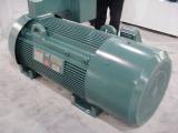
·  Polyphase Induction Motors
One third of the world's electricity consumption is used for running induction motors driving pumps, fans, compressors, elevators and machinery of various types. The AC induction motor is a common form of asynchronous motor whose operation depends on three electromagnetic phenomena:
§  Motor Action - When an iron rod (or other magnetic material) is suspended in a magnetic field so that it is free to rotate, it will align itself with the field. If the magnetic field is moving or rotating, the iron rod will move with the moving field so as to maintain alignment.
§  Rotating Field - A rotating magnetic field can be created from fixed stator poles by driving each pole-pair from a different phase of the alternating current supply.
§  Transformer Action - The current in the rotor windings is induced from the current in the stator windings, avoiding the need for a direct connection from the power source to the rotating windings.
The induction motor can be considered as an AC transformer with a rotating secondary winding.

·         Rotating Fields
Rotating magnetic fields are created by polyphase excitation of the stator windings. In the example below of a 3 phase motor, as the current applied to the winding of pole pair A (phase 1) passes its peak and begins to fall, the flux associated with the winding also begins to weaken, but at the same time the current in the winding of the next pole pair B (phase 2) and its associated flux is rising. Simultaneously the current through the winding of the previous pole pair C ( phase 3) and its associated flux will be negative and rising (towards positive). The net effect is that a magnetic flux wave is set up as the flux created by the stator poles rotates from one pole to the next, about the axis of the machine, at the frequency of the applied voltage. In other words, the rotating flux field appears to the stator as the north and south poles of a magnet rotating about the stator.


The magnitude of the rotating flux wave is proportional applied MMF. Ignoring the effect of the back EMF set up by the induced currents in the rotor windings, the flux density Bwill be proportional to the applied voltage.


·          Transformer Action
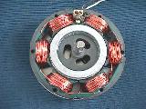
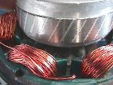
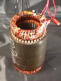
The stator carries the motor primary windings and is connected to the power source. There are normally no external connections to the rotor which carries the secondary windings. Instead the rotor windings are shorted.
When a current flows in the stator windings a current is induced in the shorted secondary windings by transformer action. The magnitude of the rotor current will be proportional to the flux density B in the air gap (and the relative motion, called the slip, of the rotor with respect to the rotating field as we shall see below).
Torque is produced by the reaction between the induced rotor currents and the air-gap flux created by the stator currents.
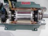
Many rotor types are used. The most popular AC motors use "squirrel cage" rotors which are constructed from copper or aluminium bars fixed between conducting end rings which provide the short circuit path for the currents induced in the bars.


Since there are no connections to the rotating windings, the costly commutator can be eliminated and with it, a potential source of unreliability.


·         Torque Generation (Motor Action)
When the motor is first switched on and the rotor is at rest, a current is induced in the rotor windings (conductors) by transformer action. Another way of seeing this is that the relative motion of the rotating flux passing over the slower moving (initially static) rotor windings causes a current to flow in the windings by generator action.
Once current is flowing in the rotor windings, the motor action due to the Lorentz force on the conductors comes into effect. The reaction between the current flowing in the rotor conductors and the magnetic flux in the air gap causes the rotor to rotate in the same direction as the rotating flux as if it was being dragged along by the flux wave.

Similar to the DC machine, the torque in an induction motor T is proportional to the flux density B and the induced rotor current I. Thus
T = k1 BI
Where k1 is a constant depending on the number of stator turns, the number of phases and the configuration of the magnetic circuit.

The rotor speed builds up due to the motor action described above, but as it does so, the relative motion between the rotating stator field and the rotating rotor conductors is reduced. This in turn reduces the generator action and thus the current in the rotor conductors and the torque on the rotor. As the speed of the rotor approaches the speed of the rotating field, known as the synchronous speed, the torque on the rotor drops to zero. Thus the speed of an induction motor can never reach the synchronous speed.

·         Slip
The relative motion between the rotating field and the rotating rotor is called the slip and is given by:
S = Ns- N
         Ns
Where S is the slip, Ns is the synchronous speed in RPM, and N is the rotor speed.

Since the rotor current is proportional to the relative motion between the rotating field and the rotor speed, the rotor current and hence the torque are both directly proportional to the slip.

The rotor current is proportional to the rotor resistance. Increasing the rotor resistance will reduce the current and increase the slip; hence a form of speed and torque control is possible with wound rotor motors. Increased rotor resistance also has the added benefit of reducing the input surge current and increasing starting torque on switch on, but all of these benefits are at the expense of more complex rotor designs and unreliable slip rings to give access to the rotor windings.

·         Speed
Synchronous speed in RPM is given by:
Ns = 120 (f)
           P
Where is the powerline frequency in Hz and is the number of poles per phase. P must be an even integer since for every north pole there is a corresponding south pole.
The following table shows motors speeds for motors with different numbers of poles working with different AC supply frequencies.

Rotor Speed (rpm)

Number of poles
2
4
6
8
10
12
Frequency 50 Hz
3000
1500
1000
750
600
500
Frequency 60 Hz
3600
1800
1200
900
720
600

The actual speed of the motor depends on the load it must drive. Increasing the load on the motor causes it to slow down increasing the slip. The motor speed will settle at an equilibrium speed when the motor torque equals the load torque. This occurs when the slip provides just enough current to deliver the required torque.

·         Speed Control
§  Pole Changing
Early machines were designed with multiple poles to facilitate speed control by pole changing. By switching in different numbers or combinations of poles a limited number of fixed speeds could be obtained.

§  Variable Rotor Resistance
The speed of induction motors can however be varied over a limited range by varying the rotor resistance as noted in the section on slip but only by using wound rotor designs negating many of the advantages of the induction motor.

§  Variable Frequency
Since motor speed depends on the speed of the rotating field, speed control can be effected by changing the frequency of the AC power supplied to the motor.

As in most machines the induction motor is designed to work with the flux density just below the saturation point over most of its operating range to achieve optimum efficiency.
The flux density B is given by:
B = k2 V
         f
Where V is the applied voltage, f is the supply frequency and k2 is a constant depending on the shape and configuration of the stator poles.
In other words if the flux density is constant, the Volts per Hertz is also a constant. This is an important relationship and it has the following consequences.
§  For speed control, the supply voltage must increase in step with the frequency, otherwise the flux in the machine will deviate from the desired optimum operating point. Practical motor controllers based on frequency control must therefore have a means of simultaneously controlling the motor supply voltage. This is known as Volts/Hertz control.
§  Increasing the frequency without increasing the voltage will cause a reduction of the flux in the magnetic circuit thus reducing the motor's output torque. The reduced motor torque will tend to increase the slip with respect to the new supply frequency. This in turn causes a greater current to flow in the stator, increasing the IR volt drop across the windings as well as the I2R copper losses in the windings. The result is a major drop in the motor efficiency. Increasing the frequency still further will ultimately cause the motor to stall.
§  Increasing the voltage without increasing the frequency will cause the material in the magnetic circuit to saturate. Excessive current will flow giving rise to high heat dissipation due to I2R losses in the windings and high eddy current losses in the magnetic circuit and ultimately failure of the motor due to overheating. Increasing the voltage will not force the motor to exceed the synchronous speed because as it approaches the synchronous speed the torque drops to zero.

The variable frequency is normally provided by an 
inverter. See more about Motor Controls

Note also that since the induced current in the rotor is proportional to the flux density and the flux density in turn is proportional to the line voltage, the torque, which depends on the product of the flux density and the rotor current, is proportional to the square of the line voltage V.

·         Generator Action
If an induction motor is forced to run at speeds in excess of the synchronous speed, the load torque exceeds the machine torque and the slip is negative, reversing the rotor induced EMF and rotor current. In this situation the machine will act as a generator with energy being returned to the supply.
If the AC supply voltage to the stator excitation is simply removed, no generation is possible because there can be no induced current in the rotor.
§  Regenerative braking
Thus in traction applications, regenerative braking is not possible below synchronous speed in a machine fed with a fixed frequency supply. If however the motor is fed by a variable frequency inverter then regenerative braking is possible by reducing the supply frequency so that the synchronous speed becomes less than the motor speed.
AC motors can be microprocessor controlled to a fine degree and can regenerate current down to almost a stop whereas DC regeneration fades quickly at low speeds.
§  Dynamic Braking
Induction motors can be brought rapidly to a stop (and / or reversed) by reversing one pair of leads which has the effect of reversing the rotating wave. This is known as "plugging". The motor can also be stopped quickly by cutting the AC supply and feeding the stator windings instead with a DC (zero frequency) supply. With both of these methods, energy is not returned to the supply but is dissipated as heat in the motor. These techniques are known as dynamic braking.

·         Starting
Three phase induction motors and some synchronous motors are not self starting but design modifications such as auxiliary or "damper" windings on the rotor are incorporated to overcome this problem.

Usually an induction motor draws 5 to 7 times its rated current during starting before the speed builds up and the current is modified by the back EMF. In wound rotor motors the starting current can be limited by increasing the resistance in series with the rotor windings.
In squirrel cage designs, electronic control systems are used to control the current to prevent damage to the motor or to its power supply.
Even with current control the motor can still overheat because, although the current can be limited, the speed build up is slower and the inrush current, though reduced, is maintained for a longer period.

·         Power Factor
The current drawn by an induction motor has two components, the current in phase with the voltage which governs the power transfer to the load and the inductive component, representing the magnetising current in the magnetic circuit, which lags 90° behind the load current.
The power factor is defined as cosΦ where Φ is the net lag of the current behind the applied voltage due to the in phase and out of phase current components. The net power delivered to the load is VAcosΦ where V is the applied voltage, A is the current which flows.

Various methods of power factor correction are used to reduce the current lag in order to avoid losses due to poor power factor. The simplest is to connect a capacitor of suitable size across the motor terminals. Since the current through a capacitor leads the voltage, the effect of the capacitor is to counter-balance the inductive element in the motor canceling out the current lag.
Power factor correction can also be accomplished in the motor controller.

·         Characteristics
One of the major advantages of the induction motor is that it does not need a commutator. Induction motors are therefore simple, robust, reliable, maintenance free and relatively low cost.
They are normally constant speed devices whose speed is proportional to the mains frequency.
Variable speed motors are also possible by using motor controllers which provide a variable frequency output.

·         Applications
Three phase induction motors are used wherever the application depends on AC power from the national grid. Because they don't need commutators they are particularly suitable for high power applications.
They are available with power handling capacities ranging from a few Watts to more than 10 MegaWatts.
They are mainly used for heavy industrial applications and for machine tools.
The availability of solid state inverters in recent years means that induction motors can now be run from a DC source. They are now finding use in automotive applications for electric and hybrid electric vehicles. Nevertheless, the induction motor is ill-suited for most automotive applications because of the difficulties associated with extracting heat from the rotor, efficiency problems over wide speed and power ranges, and a more expensive manufacturing process due to distributed windings. Permanent magnetand reluctance motors offer better solutions for these applications.

Wound Rotor Induction Motor
Now of historic interest only, these motors were designed to permit control of the speed - torque characteristics of the machine. They used conventional windings on the rotor which were accessible through slip rings. The rotor windings were not connected to the supply line but current through the windings could be controlled by external rheostats connected in series with the windings. Modern electronic controls have made these designs obsolete.

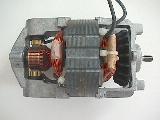
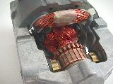
Single Phase Induction Motors
At first sight it might be assumed that it would be impossible to create a rotating field using only a single phase supply. With the aid of an auxiliary stator winding displaced from the main winding it is however possible to create a second MagnetoMotive Force (MMF) in the auxiliary winding, out of phase with the MMF in the main winding, and this is sufficient to generate the rotating field.
·         Capacitor-Run Motors
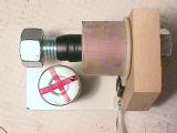
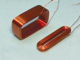
The necessary phase difference between the main and auxiliary windings can be provided by connecting a high value capacitor in series with the auxiliary winding. These motors are commonly used in household washing machines, refrigerators and shower pumps and can easily be identified by the large electrolytic capacitor strapped to the motor body.
As an alternative to using an external capacitor, the split-phase method uses a high resistance auxiliary winding. The difference in the impedance of the two windings is sufficient to create the necessary phase difference between the currents in the two windings.
·         Shaded Pole Motors
The shaded pole motor uses another, rather crude, method of inducing a second stator MMF, out of phase with the main MMF in order to create the desired rotating field from a single phase AC supply. A short circuited turn of thick copper, known as the shading ring, is mounted in a slot in the pole piece. Some of the magnetic flux produced by the main winding induces a current in the shading ring which produces its own weak flux which opposes and retards the main flux through the ring so that the resulting flux through the ring is out of phase with the main flux. Thus there is a phase difference between one side of the pole and the other. Though inefficient, this method is once more sufficient to set up a rotating field.


§  Characteristics
Single phase induction motors are less efficient than polyphase machines and were developed mainly for domestic use since most dwellings are only supplied with single phase power.
No control of speed.
§  Applications
All kinds of household appliances and light industrial applications.

Synchronous AC Motors
The synchronous motor is similar to the induction motor in that it is a polyphase machine in which the stator produces a rotating field, however the rotor is constructed from either permanent magnets or electromagnets energised by direct current supplied through slip rings. 
·         Torque
The torque depends on the attraction of the rotor magnets to the rotating magnetic poles and not on relative motion between the windings in the rotor and the rotating magnetic field. It can therefore lock on to the rotating field. See Alternative Motor Action. Unlike squirrel cage induction motors, synchronous motors can run and produce torque at synchronous speed.
They are difficult to start on mains frequency because the rotating field is too fast so they need to start at lower frequency or they need unexcited auxiliary windings or a rudimentary squirrel cage to bring the rotor up to synchronous speed. As the motor approaches synchronous speed it will suddenly snap in to synchronisation.
§  Pull In Torque
To achieve synchronisation the motor torque must be greater then the load torque. The torque developed when the motor locks on to synchronous speed is called the pull in torque. If the load is greater than the pull in torque the motor will not reach synchronous speed.
§  Pull Out Torque
As the load on the motor is increased, the motor torque and the torque angle will also increase. However if the torque angle exceeds 90 degrees the torque will begin to fall and the motor will lose synchronisation and eventually stop. The pull out torque is typically 1.5 times the continuously rated torque.

·         Characteristics
Synchronous operation.
·         Applications
Fixed speed applications such as clocks and timers
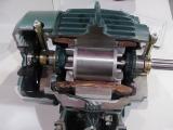
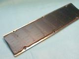
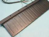
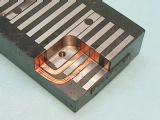
Synchronous Reluctance Motors
The operating principle of the basic reluctance motors is described in the section about switched reluctance motors.
The so called "synchronous" reluctance motor is designed to run on mains frequency alternating current and it uses distributed stator windings similar to those used in squirrel cage induction motors. The rotor however needs salient poles to create a variable reluctance in the motor's magnetic circuit which depends on the angular position of the rotor. These salient poles can be created by milling axial slots along the length of a squirrel cage rotor. See diagram below.


·         Characteristics
The synchronous reluctance motor is not self starting without the squirrel cage. During run up it behaves as an induction motor but as it approaches synchronous speed, the reluctance torque takes over and the motor locks into synchronous speed.
·         Applications
Used where regulated speed control is required in applications suc as metering pumps and industrial process equipment.

Hysteresis Motor
The Hysteresis Synchronous motor consists of a wound stator producing a rotating field and a rotor in the form of a cylindrical shell with crossbars all made from hard steel with relatively high magnetic hysteresis.


At start up, the combined effects of eddy currents in the steel causing induction motor action and remanent magnetism in the steel causing the magnetic poles to follow the rotating field, together cause the motor speed to build up. As the motor approaches synchronous speed the magnetic effect of the crossbars behaving like a permanent magnet causes the motor to lock on to synchronous speed. The net result is that the torque is roughly constant at all speeds.

·         Characteristics
Simple design
Starts as an induction motor and locks in as a synchronous motor.
Having a smooth rotor of homogenous material, the noise and vibration produced is inherently low. Since there are no pole faces or saliencies, the magnetic path is of constant permeability, thus eliminating the magnetic pulsations which are the major cause of noise in the salient pole type.
·         Applications
Their efficiency is low, and applications are restricted to small power ratings.
Used extensively in tape recorders and clocks.
Now mostly replaced by permanent magnet motors.

Universal Motors
An AC motor which uses separately excited rotor windings using a commutator to feed current to rotor coils behaves in much the same way as a brushed DC motor and can in fact be used as a universal motor taking its supply either from an AC or a DC source.
Unlike induction and synchronous motors, the speed of universal motors is not limited by the electric mains supply frequency and can easily exceed one revolution per cycle. This makes them useful for household appliances such as blenders, vacuum cleaners and hair dryers which need high-speed operation. Speeds of up to 30,000 RPM are possible but the current carrying capacity is limited by the commutator and brushes which restricts their use to low power applications of about 1 kilowatt or less